EMI shielding on a PCB usually comes down to a few methods: conductive foam, gaskets, or spring contacts. Each grounds a shield can or enclosure to the board. They do not perform equally over the life of a product, and the difference only appears after the product has been in service for a while.
CONDUCTIVE FOAM AND GASKETS
- Forgiving of tolerance: They accommodate larger and less consistent gaps without precise alignment, which simplifies mechanical design.
- Continuous contact: A gasket seals along a length rather than at points, which suits an enclosure seam.
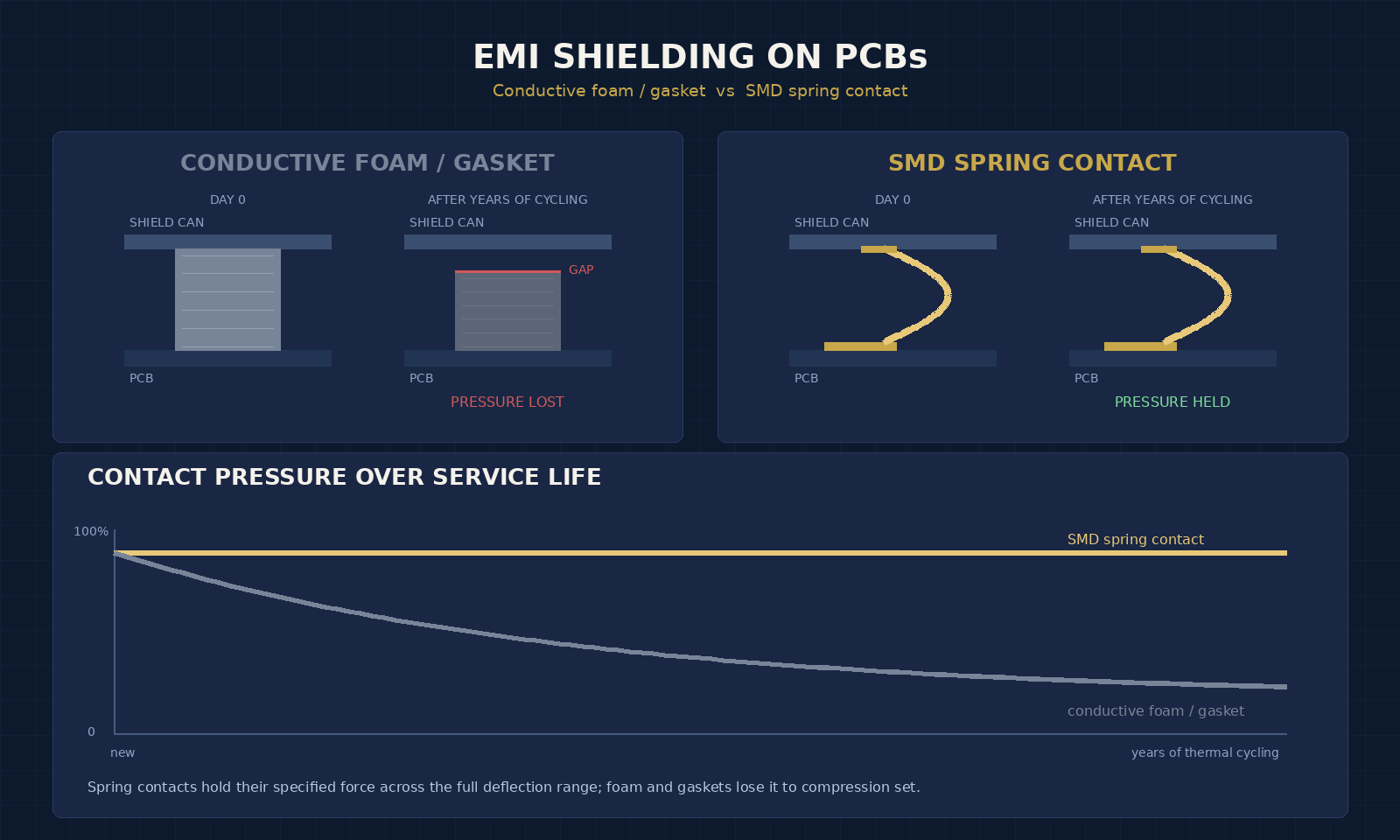
- They degrade under load: Compression set is the limitation. Held compressed through years of thermal cycling, the material loses height and the contact pressure falls with it.
That last point is the whole issue. The shielding performance depends on contact pressure, so a material that relaxes delivers less shielding at year five than at week one — and nothing about the assembly looks different.
SMD SPRING CONTACTS
- Elastic rather than compressive: Within its specified deflection range, a spring contact returns the same force after every cycle.
- Defined force: Contact force is a specified property with a tolerance, rather than a consequence of how much the material was squashed.
- Placed automatically: Supplied in tape-and-reel for pick-and-place and standard SMT reflow, so they fit an existing assembly process.
- Less forgiving of gap variation: The trade. A contact has a working deflection range, and the gap must stay inside it.
THE FAILURE MODE THAT DECIDES IT
Both approaches fail the same way electrically: contact resistance rises, and shielding effectiveness falls with it. What differs is why.
Foam and gaskets fail through compression set — permanent loss of thickness under sustained load, accelerated by heat. Spring contacts fail through stress relaxation if the material is unsuited to the temperature, or through fretting corrosion if the plating is wrong for a joint that vibrates.
The difference is that a spring contact's failure modes are addressable by specification. Choosing beryllium copper for temperature and gold plating for micro-motion largely removes both. Compression set in a foam is a property of the material and cannot be specified away.
WHICH TO SPECIFY
Use foam or a gasket where the gap is variable or poorly controlled, where a continuous seal along a seam is needed, or where the service life is short enough that compression set will not matter.
Use a spring contact where the gap is controlled, where the service life is long, where the environment cycles thermally, or where the contact force needs to be a specified and repeatable value. Automotive and industrial applications usually fall here.
WHAT TO WORK OUT FIRST
- The compressed gap at nominal and at both tolerance extremes, calculated through the full stack rather than at nominal alone.
- The service life and the temperature range across it.
- Whether the joint experiences vibration or micro-motion, which decides plating.
- Available footprint and keep-out on the board.
If the gap variation turns out to be wider than any contact's deflection range, that is a mechanical design finding rather than a component selection problem, and it is much cheaper to discover at this point than after the first build.
A NOTE ON MEASURING SHIELDING EFFECTIVENESS
Comparing two grounding methods on paper is easy. Comparing them meaningfully requires deciding what you measure and when.
Contact resistance should be measured with a four-wire method at the current the joint will carry. A two-wire measurement includes lead resistance, which on a milliohm-level contact swamps the reading entirely.
Measure after ageing, not on new parts. This is the decisive point in any foam-versus-contact comparison, because on day one both perform well. Age the samples at the maximum service temperature for a defined period under working compression, then re-measure force and resistance. That is the test that separates them.
A comparison run only on new samples will conclude that foam is adequate, and it will be wrong in the way that matters.
OUR RANGE
Beryllium copper throughout, 31 variants across 57 part numbers, heights from 1.5 mm to 13.0 mm, in tin or gold plating, tape-and-reel packaged. Send the compressed gap with tolerances, the footprint available, the operating temperature range, and whether your process requires tin or gold, and we can point at a specific part number.
Send us your board layout, shielding requirements, or contact specifications and our engineering team — backed by 20+ years of spring and electronic contact manufacturing — will get back to you with a competitive quote and realistic turnaround.
Email: sales@seyunda.com
Phone: +65 9168 2618
We look forward to supporting your next PCB program.
Published by the Seyunda Team · 2026