ADAS hardware puts radar, camera, and sensor-fusion modules in places on a vehicle that were previously just structure. Each module needs its electronics shielded, and each shield needs a reliable ground path to the board or enclosure. That path is often an SMD spring contact.
WHY GROUNDING IS THE ADAS PROBLEM
An EMI shield can only work if it is properly grounded. An enclosure at a floating potential is not a shield — it can behave as an antenna. The contact between shield and ground plane therefore is the shielding, and its quality over the vehicle's life determines whether the module keeps meeting its EMC requirement.
What makes automotive harder than consumer electronics is duration and environment. A phone shield needs to work for a few years in a pocket. A radar module needs to work for fifteen years through thermal cycling, vibration, and humidity.
WHY SPRING CONTACTS RATHER THAN FOAM OR GASKETS
Conductive foam and gaskets accommodate larger tolerance gaps and are forgiving of alignment. Their weakness is compression set: held compressed over years of thermal cycling, they lose height and the contact pressure falls with it.
A spring contact works elastically. Within its specified deflection range it returns the same force after each cycle. That is the property that matters across a fifteen-year service life, and it is the reason automotive shielding tends toward contacts where the gap is controlled enough to allow them.
WHAT TO SPECIFY, IN ORDER
- The compressed gap at nominal and both tolerance extremes. A contact that only just touches at maximum gap has no margin.
- Working deflection within the elastic range at minimum gap. Compressed solid, beryllium copper takes a permanent set and the force does not return.
- Footprint and keep-out against available board area.
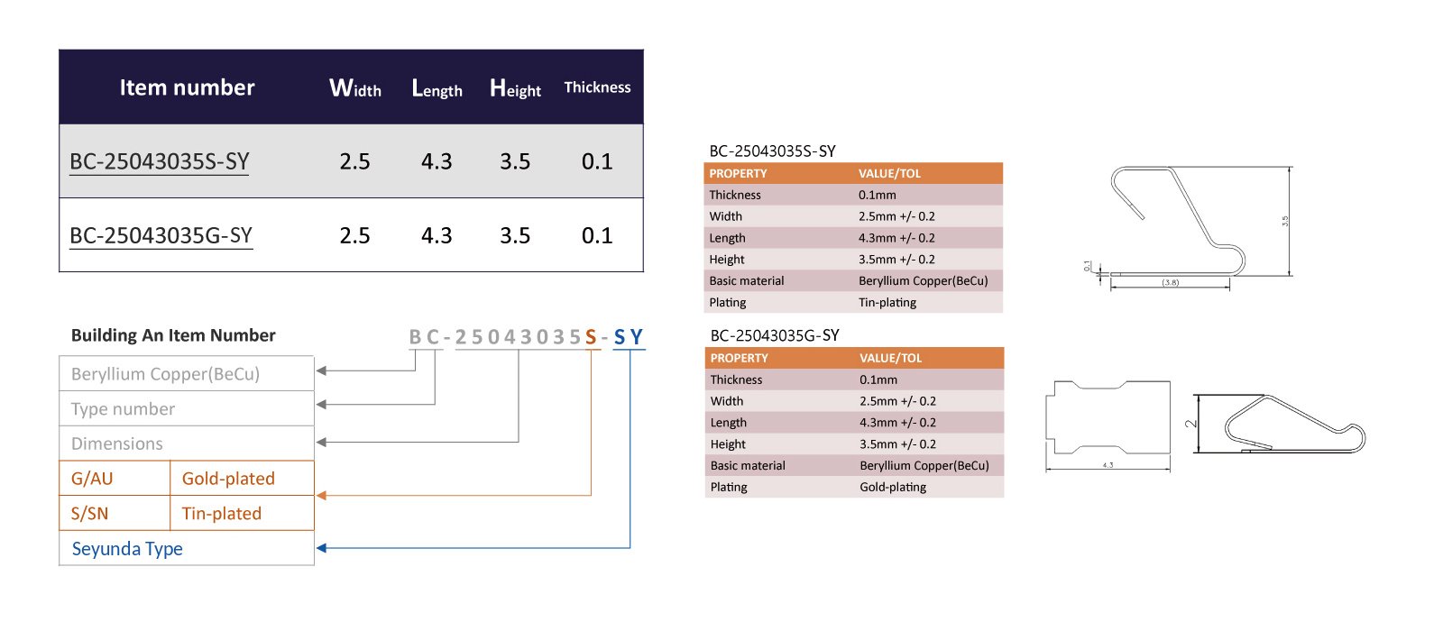
- Plating. Gold where contact resistance must stay stable and the joint sees vibration; tin where the environment is benign and cost matters.
For a vibrating automotive assembly, gold is usually the more durable answer. Tin under repeated micro-motion is subject to fretting corrosion, where tin oxide accumulates at the interface and resistance climbs — precisely the failure that shows up as an intermittent EMC problem years into service.
WHY BERYLLIUM COPPER
All 31 of our contact variants are beryllium copper. C17200 in the precipitation-hardened condition gives about 22% IACS conductivity with an exceptional elastic limit and resistance to stress relaxation at elevated temperature. That last property is the automotive-relevant one: a contact in an engine bay or behind a grille must still deliver its specified force after years at temperature.
THE TOLERANCE STACK THAT DECIDES THE GAP
The compressed gap a contact must bridge is rarely a single dimension. It accumulates: PCB thickness tolerance, shield can height tolerance, solder joint height, board warp, and the mounting tolerance of the assembly around it.
Calculating the gap at nominal and assuming it holds is the most common specification error we see. The worst-case maximum gap is what determines whether contact is maintained at all, and the worst-case minimum determines whether the contact is compressed beyond its elastic range.
Work the stack at both extremes before selecting a part number. A contact chosen on the nominal gap will work on the bench and produce a field return rate that nobody can reproduce, because the failures are at the tolerance extremes of the build population rather than in the middle.
RANGE AND SELECTION
Our contacts cover heights from 1.5 mm to 13.0 mm across 57 part numbers, with the taller stand-offs in the Type 3 and S family. All are supplied in tape-and-reel for automated pick-and-place and standard SMT reflow.
Send the compressed gap with tolerances, available footprint, operating temperature range, expected cycles, and whether your process needs tin or gold. Those five answers usually identify a specific part number from the existing range.
One process point worth confirming early. Contacts are supplied in tape-and-reel for automated placement and go through standard SMT reflow, which means the reflow profile has to suit the contact as well as the components around it. Confirm the profile against the contact specification before the first build, particularly where a board carries mixed thermal mass and the profile has already been optimized for something else.
Send us your drawings, specifications, or automotive program requirements and our engineering team — backed by 20+ years in precision springs and machinery, IATF 16949 certified since 2021 — will get back to you with a competitive quote and realistic turnaround.
Email: sales@seyunda.com
Phone: +65 9168 2618
We look forward to supporting your next automotive program.
Published by the Seyunda Team · 2026