An SMD spring contact is a small stamped-and-formed part that does one job well: it holds a reliable electrical path between two moving surfaces. It grounds a shield can to a PCB. It bridges a board to a chassis. It carries a signal to a battery contact or a flexible assembly. The part is only a few millimeters across. When it is specified wrongly, the symptom is an intermittent fault in the field — the most expensive kind to diagnose.
Seyunda publishes 31 variants across 57 part numbers, in three families. This is how to tell them apart, and how to choose.
WHAT ALL 31 VARIANTS SHARE
Before looking at the differences, here are the constants. They narrow the decision considerably:
- Beryllium copper (BeCu) throughout: Every one of the 31 variants uses it. Nothing in the range is phosphor bronze or stainless.
- Stock thickness of 0.08 – 0.15 mm: Thicker stock gives more contact force for the same geometry. It also means less deflection before the part takes a permanent shape.
- Tin or gold plating: Most part numbers are gold. A subset is available tin-plated. The final letter of the part number tells you which is which.
- Tape-and-reel packaging: This allows for automated pick-and-place and standard SMT reflow assembly.
HOW THE THREE FAMILIES DIFFER
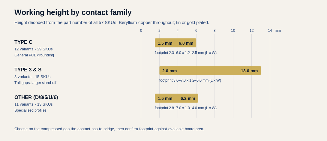
- Type C (12 variants, 29 part numbers): This is the general-purpose family and the best place to start. Heights range from 1.5 to 6.0 mm on footprints from 2.3 x 1.2 mm up to 6.0 x 2.5 mm. It also carries most of the tin-plated options. If your process requires tin rather than gold, look here first.
- Type 3 & S (8 variants, 15 part numbers): This is the tall family. Heights run from 2.0 to 13.0 mm. Nothing else in the catalog reaches beyond 6.2 mm. Footprints go wider too, up to 7.0 x 5.0 mm. If the gap you have to bridge is more than about 6 mm when compressed, this is the only family that will work.
- Other types (11 variants, 13 part numbers): This includes Types D, 8, 5, U, and 6. These are specialized profiles for particular mounting or clearance constraints. Heights range from 1.5 to 6.2 mm. Most have single part numbers per variant, so they are chosen for their unique shape rather than a wide range of sizes.
START WITH THE GAP, NOT THE PART NUMBER
The most common design mistake is picking a contact by its footprint because board space is tight, then discovering it cannot reach the target. Always work in this exact order:
- Measure the compressed gap the contact must bridge. Do this at nominal height and at both tolerance extremes. A contact that just barely touches at maximum gap is bound to fail.
- Allow working deflection. The contact must stay in its elastic range at the minimum gap. If compressed solid, beryllium copper will take a permanent set, and the spring force will never come back.
- Check the footprint against your available pad area and keep-out zones.
- Choose your plating.
Getting this order wrong produces a design that passes on the test bench but fails after six months of temperature changes in the field.
READING THE PART NUMBER
The part numbering encodes the geometry. This makes it possible to check a quotation without opening a datasheet. The pattern is XX-WWLLLHHH{G|S}-SY:
- XX: Family code. BC for Type C; B3 and BS for Type 3 and S; BD / B8 / B5 / BU / B6 for the other profiles.
- WW: Width in tenths of a millimeter. (25 = 2.5 mm).
- LLL: Length in tenths of a millimeter. (043 = 4.3 mm).
- HHH: Height in tenths of a millimeter. (035 = 3.5 mm).
- G or S: Gold or Tin plating.
For example, BC-25043035G-SY is a Type C contact that is 2.5 mm wide, 4.3 mm long, and 3.5 mm high with gold plating. The dimensional tolerance is ±0.2 mm. If a part number and a dimension table ever disagree, one of them is a typo — and it is always worth asking which one is correct.
TIN OR GOLD PLATING
Gold plating is specified where contact resistance must stay low and stable over a long service life. This is vital in low-current signal paths where even a thin oxide layer can disrupt the signal. It is also necessary in environments with high humidity or corrosion risks. Gold does not oxidize. The connection it forms on day one will be just as good in year five.
Tin costs less and solders easily. It is a solid choice for grounding paths where a small, stable contact resistance is acceptable and the environment is safe. The main risk to weigh is fretting corrosion. Under repeated micro-movements, tin oxide builds up at the connection point and resistance climbs. If your assembly vibrates or changes temperature against a mating surface, gold is the safer choice.
WHY BERYLLIUM COPPER MATTERS
BeCu is the industry standard for this application because it has a rare combination of traits: high electrical conductivity and a high elastic limit after age hardening. This allows a thin section of metal to bend repeatedly without losing its spring shape. A contact stamped from ordinary brass would either be too soft to hold its force or too brittle to survive assembly. That elastic recovery is the core of the product. It keeps steady contact pressure on the mating surface after thousands of cycles.
WHAT TO SEND US FOR A QUOTE
A useful engineering inquiry needs four things:
- The compressed gap size with tolerances.
- The available footprint space and keep-out zones.
- The operating environment (temperature range, vibration, humidity, and expected lifetime cycles).
- Whether your process requires tin or gold plating.
With these details, we can point you to a specific part number from our 57 options. If our standard range does not cover it, we will tell you honestly and suggest a custom profile.
Send us your drawings, samples, or requirements and our engineering team — backed by 20+ years of spring and machinery manufacturing experience — will get back to you with a competitive quote and realistic turnaround.
Email: sales@seyunda.com
Phone: +65 9168 2618
We look forward to supporting your next project.
Published by the Seyunda Team · 2026