Advanced driver assistance systems put radar, cameras, and high-speed processing into a vehicle in numbers that would have been implausible a decade ago — and place them close together, in metal enclosures, in an environment of vibration and thermal cycling.
That combination raises the electromagnetic compatibility requirement substantially, and it changes what a shielding contact has to do.
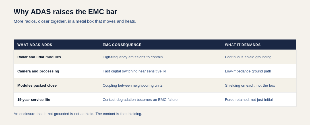
WHY MORE MODULES MEANS MORE THAN MORE SHIELDING
Each additional module is both a potential emitter and a potential victim. Radar operates at high frequency; camera and processing electronics switch fast digital signals. Put them near each other and the coupling problem is not additive but combinatorial — every new module is a new pair with every existing one.
The practical response is shielding at the module level rather than relying on the vehicle enclosure. Each unit contains its own emissions and protects itself from its neighbors, which is why the count of shield cans in a vehicle has risen faster than the count of modules.
A SHIELD IS ONLY A SHIELD IF IT IS GROUNDED
This is the point that connects EMC engineering to a small mechanical component. A shield can at a floating potential does not attenuate; it can re-radiate, behaving as an antenna rather than a barrier.
The shield's effectiveness therefore depends on the impedance of its connection to ground. That connection is frequently a spring contact, and the contact's resistance depends on the pressure it maintains against the mating surface.
Which makes contact force an EMC parameter, not just a mechanical one. When force decays, contact resistance rises, and shielding performance degrades with it.
WHAT FIFTEEN YEARS DOES
Consumer electronics need shielding to work for a few years in a benign environment. A vehicle module has to hold its EMC performance across a service life of well over a decade, through thermal cycling, vibration, and humidity.
Two mechanisms degrade a contact over that period. Stress relaxation — the material loses force under sustained load at temperature. And fretting corrosion — under micro-motion, oxide accumulates at the interface and resistance climbs. Both are slow, both are invisible on a new part, and both produce the same symptom: an EMC problem that appears years into service and cannot be reproduced on the bench.
WHY THIS FAVORS SPRING CONTACTS
Conductive foam and gaskets accommodate larger gaps and forgive alignment. Their weakness is compression set: held compressed over years of thermal cycling, they lose height and pressure falls with it.
A spring contact works elastically. Within its specified deflection range it returns the same force after each cycle, which is the property that matters across a vehicle service life. Beryllium copper is the usual material because it holds its elastic properties at temperature better than the alternatives.
WHY THIS FAILURE IS SO HARD TO DIAGNOSE
Contact degradation produces the most difficult category of field problem: intermittent, environment-dependent, and not reproducible on the bench.
A module that passes EMC testing at launch can fail years later because contact resistance has risen. By then the symptom is a customer complaint about interference or a sensor fault, and the investigation looks at software, at the sensor, and at the harness long before it looks at a small piece of beryllium copper.
Worse, the failure is often temperature dependent, so the unit behaves correctly on a test bench and misbehaves in a hot engine bay. That is the signature of a contact problem, and it is worth adding to the diagnostic list earlier than most teams do.
The prevention is entirely at design stage: specify contact force at service temperature, choose plating for the vibration environment, and work the gap stack at its extremes rather than at nominal.
WHAT TO GET RIGHT AT DESIGN STAGE
- Work the gap tolerance stack at both extremes, not at nominal. The maximum decides whether contact is maintained; the minimum decides whether the contact is over-compressed.
- Specify contact force at the operating temperature, not at ambient.
- Choose plating for the vibration environment. Gold where micro-motion is expected, which in a vehicle is most places.
- Treat the ground path as a circuit with an impedance, rather than as a mechanical attachment.
For contact selection across our 31 variants and 57 part numbers, our SMD contacts guide covers the specifics of type, height, and plating.
Send us your drawings, samples, or requirements and our engineering team — backed by 20+ years of spring and machinery manufacturing experience — will get back to you with a competitive quote and realistic turnaround.
Email: sales@seyunda.com
Phone: +65 9168 2618
We look forward to supporting your next project.
Published by the Seyunda Team · 2026